Basic Shaders
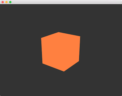
It's time to graduate to writing our own shaders. Much of the power of realtime graphics lies in custom shaders. While we only have space to give a very high-level overview of shaders, this should be enough to get started. First, a shader is a program (written in GLSL in the case of OpenGL) which runs on the GPU. This is as opposed to your C++ code, which of course runs on the CPU. In the general case, to create a complete GLSL Program, we need to supply two kinds of shaders - a vertex shader, and a fragment shader. The first, the vertex shader, operates on each vertex of whatever geometry we're applying it to. The fragment shader operates on each pixel, which (typically) are interpolated across a triangle when the geometry is rasterized. Without getting too bogged down in details yet, let's look at a minimal shader that outputs orange pixels:
class BasicApp : public App {
  public:
	void	setup() override;
	void	draw() override;

	CameraPersp         mCam;
	gl::BatchRef        mCube;
	gl::GlslProgRef		mGlsl;
};

void BasicApp::setup()
{
	mCam.lookAt( vec3( 3, 2, 4 ), vec3( 0 ) );

	mGlsl = gl::GlslProg::create( gl::GlslProg::Format()
	.vertex(	CI_GLSL( 150,
		uniform mat4	ciModelViewProjection;
		in vec4			ciPosition;

		void main( void ) {
			gl_Position	= ciModelViewProjection * ciPosition;
		}
	 ) )
	.fragment(	CI_GLSL( 150,
		out vec4			oColor;

		void main( void ) {
			oColor = vec4( 1, 0.5, 0.25, 1 );
		}
	) ) );

	mCube = gl::Batch::create( geom::Cube(), mGlsl );

	gl::enableDepthWrite();
	gl::enableDepthRead();
}

void BasicApp::draw()
{
	gl::clear( Color( 0.2f, 0.2f, 0.2f ) );
	gl::setMatrices( mCam );
	mCube->draw();
}
There's a number of new concepts wrapped up in this short sample. Recall that previously we were creating a gl::GlslProg using the function gl::getStockShader() and the gl::ShaderDef class. Now we're using the gl::GlslProg::create() method, passing it a gl::GlslProg::Format, which in turn was constructed using the CI_GLSL macro for both vertex() and fragment(). This macro is a convenient way to write GLSL code inline with our C++ code. Note that its first argument is the numer 150. This specifies the version of GLSL we're writing. Since we're targeting OpenGL version 3.2 or later, we're writing version 150 of GLSL. Slightly confusing, but this table should clarify if you're interested. We'll look at the actual GLSL code below. Note however that for the most part, the application is similar to examples we've looked at in previous sections. We still create a gl::Batch, this time using a geom::Cube and our mGlsl variable as parameters. We still call gl::setMatrices() to setup our camera, and we'll see what this does behind the scenes shortly.
The role of the vertex shader is twofold. First, it's responsible for expressing what attributes we want to be available to the fragment shader. For example, if we want a different color for each vertex, we'd need to output that from the vertex shader. We'll look into this more later. The vertex shader's other role is to take vertex positions expressed in Object space and output them as positions in Clip space. If this term is not familiar to you, Clip space is essentially the coordinate system representing points which have been transformed into World space (via the Model matrix), then transformed from World into View space (via the View matrix) and then projected onto the screen (via the Projection matrix). All three of these transformations can be encoded into a single matrix, which is the ModelViewProjection matrix. In Cinder you can access this matrix with gl::getModelViewProjection().
Let's look at the vertex shader code in detail. First the line uniform mat4 ciModelViewProjection; introduces an unfamiliar keyword. uniforms are simply variables that are passed into the shader "from C++". Later examples will show how to pass custom uniforms yourself, but there are several uniforms which Cinder passes to your shader automatically when you name them a specific name. In this case, a uniform named ciModelViewProjection will automatically receive the current ModelViewProjection matrix from Cinder. Next, the line in vec4 ciPosition; introduces the in keyword, which declares a variable to be per-vertex data supplied by the draw call. In our case, we're calling mCube->draw(), which uses the vertex data supplied by geom::Cube. Similar to the uniform, because this variable is named ciPosition, Cinder automatically knows how to supply it with the relevant position data - that generated by the geom::Cube in this particular case. Next we see a main() declaration which is simply how we declare the actual code of our shader, much like one would in C or C++. Finally, our one-line implementation, gl_Position = ciModelViewProjection * ciPosition;. This line sets the built-in variable gl_Position, which must always be set by a vertex shader to specify the final position in Clip space. This variable is set to its canonical value; we transform our input vertex position (expressed in Object space) into Clip space by multiplying it by the ModelViewProjection matrix.
Finally, we'll look at the fragment shader, whose job is to set a final pixel color. We first encounter an out variable called oColor, which in the case of a fragment shader records its result. Our one-line implementation simply sets this variable oColor to a constant value representing the color orange.
Let's keep moving by looking at how variables can be interpolated across a polygon using the vertex shader:
class BasicApp : public App {
  public:
	void	setup() override;
	void	draw() override;

	CameraPersp         mCam;
	gl::BatchRef        mRect;
	gl::GlslProgRef		mGlsl;
};

void BasicApp::setup()
{
	mCam.lookAt( vec3( 2, 1, 3 ), vec3( 0 ) );

	mGlsl = gl::GlslProg::create( gl::GlslProg::Format()
	.vertex(	CI_GLSL( 150,
		uniform mat4	ciModelViewProjection;
		in vec4			ciPosition;
		in vec4			ciColor;
		out vec4		Color;

		void main( void ) {
			gl_Position	= ciModelViewProjection * ciPosition;
			Color = ciColor;
		}
	 ) )
	.fragment(	CI_GLSL( 150,
		in vec4		Color;
		out vec4	oColor;

		void main( void ) {
			oColor = Color;
		}
	) ) );

	auto rect = geom::Rect().colors( Color( 1, 0, 0 ),
									 Color( 0, 0, 1 ),
									 Color( 0, 0, 1 ),
									 Color( 1, 0, 0 ) );
	mRect = gl::Batch::create( rect, mGlsl );

	gl::enableDepthWrite();
	gl::enableDepthRead();
}

void BasicApp::draw()
{
	gl::clear( Color( 0.2f, 0.2f, 0.2f ) );
	gl::setMatrices( mCam );
	mRect->draw();
}
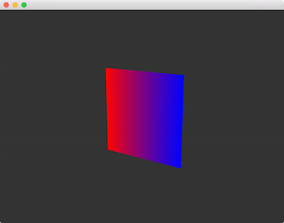
Much of this sample is similar to the previous, but a couple of key concepts are illustrated. A red to blue gradient is created by using the colors() method on geom::Rect, which allows us to specify a different color for each corner, starting in the upper left and moving sequentially clockwise through the vertices. Note that the geom::Rect is defined in the XY-plane, but we're using a 3D CameraPersp to view it at an angle.
The key changes here though are in the shaders. The first change is the addition of a new in variable ciColor in the vertex shader. Much like ciPosition, this is a per-vertex attribute which Cinder automatically recognizes and supplies. Additionally, a new out variable Color has been added. out variables in a vertex shader are interpolated across the vertices that form a given triangle (or in some cases, line) and are made available to the subsequent fragment shader. We're choosing to define and interpolate color in this case, and this occurs in the body of the shader in the very simple line, Color = ciColor;. Another way to read this line might be, "make the output, interpolated color value match this vertex's input color value." It's in the fragment shader that this value is utilized. There we see a matching in variable, defined with the line in vec4 Color - the matching in variable for the vertex shader's out. In the fragment shader's body, we simply assign the output color oColor to be the same as this fragment's interpolated Color value. The final result in our case is a gradient across the rectangle.
Next we'll look at how to send data from your C++ code to a GLSL program.
class BasicApp : public App {
  public:
	void	setup() override;
	void	draw() override;

	CameraPersp			mCam;
	gl::BatchRef		mRect;
	gl::GlslProgRef		mGlsl;
};

void BasicApp::setup()
{
	mCam.lookAt( vec3( 3, 2, 3 ), vec3( 0 ) );

	mGlsl = gl::GlslProg::create( gl::GlslProg::Format()
	.vertex(	CI_GLSL( 150,
		uniform mat4	ciModelViewProjection;
		in vec4			ciPosition;

		void main( void ) {
			gl_Position	= ciModelViewProjection * ciPosition;
		}
	 ) )
	.fragment(	CI_GLSL( 150,
		uniform vec4	uColor;
		out vec4		oColor;

		void main( void ) {
			oColor = uColor;
		}
	) ) );

	mRect = gl::Batch::create( geom::Plane(), mGlsl );

	gl::enableDepthWrite();
	gl::enableDepthRead();
}

void BasicApp::draw()
{
	gl::clear( Color( 0.2f, 0.2f, 0.2f ) );
	gl::setMatrices( mCam );

	const int NUM_PLANES = 30;
	for( int p = 0; p < NUM_PLANES; ++p ) {
		float hue = p / (float)NUM_PLANES;
		ColorAf color( CM_HSV, hue, 1, 1, 1 );
		mGlsl->uniform( "uColor", color );

		gl::ScopedModelMatrix scpMtx;
		float angle = M_PI * p / (float)NUM_PLANES;
		gl::rotate( angleAxis( angle, vec3( 1, 0, 0 ) ) );
		mRect->draw();
	}
}
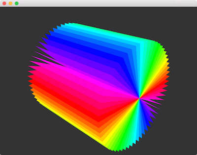
From a high level, this example creates a batch with our custom shader and a geom::Plane. It makes 30 copies of this plane, rotating each around the Z-axis, and assigning a different color. In many ways this is similar to examples we looked at in previous sections, but the key difference here of course is that we're using a custom shader. In particular, we're using a custom uniform. Whereas uniforms like ciModelViewProjection are automatically supplied by Cinder, here we've created a new uniform uColor, declared and used in the fragment shader. The way we're using from GLSL it is straightforward. The interesting bit lies in the C++ code, specifically the for-loop inside draw(). Here we call the uniform() function, passing it a ColorAf called color. Calling this function (and its many siblings) allows us to send a variable from our C++ code to the shader.
Next we'll look at how to use textures from shaders.
void BasicApp::setup()
{
	mCam.lookAt( vec3( 3, 2, 3 ), vec3( 0 ) );

	auto img = loadImage( loadAsset( "texture.jpg" ) );
	mTex = gl::Texture2d::create( img );
	mTex->bind( 0 );

	mGlsl = gl::GlslProg::create( gl::GlslProg::Format()
	.vertex(	CI_GLSL( 150,
		uniform mat4	ciModelViewProjection;
		in vec4			ciPosition;
		in vec2			ciTexCoord0;
		out vec2		TexCoord0;

		void main( void ) {
			gl_Position	= ciModelViewProjection * ciPosition;
			TexCoord0 = ciTexCoord0;
		}
	 ) )
	.fragment(	CI_GLSL( 150,
		uniform vec4		uColor;
		uniform sampler2D	uTex0;

		in vec2				TexCoord0;
		out vec4			oColor;

		void main( void ) {
			oColor = texture( uTex0, TexCoord0 ) * uColor;
		}
	) ) );

	mRect = gl::Batch::create( geom::Plane(), mGlsl );

	gl::enableDepthWrite();
	gl::enableDepthRead();
}

void BasicApp::draw()
{
	gl::clear( Color( 0.2f, 0.2f, 0.2f ) );
	gl::setMatrices( mCam );

	const int NUM_PLANES = 7;
	for( int p = 0; p < NUM_PLANES; ++p ) {
		float hue = p / (float)NUM_PLANES;
		ColorAf color( CM_HSV, hue, 1, 1, 1 );
		mGlsl->uniform( "uTex0", 0 );
		mGlsl->uniform( "uColor", color );

		gl::ScopedModelMatrix scpMtx;
		float angle = M_PI * p / (float)NUM_PLANES;
		gl::rotate( angleAxis( angle, vec3( 1, 0, 0 ) ) );
		mRect->draw();
	}

	gl::setMatricesWindow( getWindowSize() );
	gl::draw( mTex, Rectf( 0, getWindowHeight() - 100,
							150, getWindowHeight() ) );
}
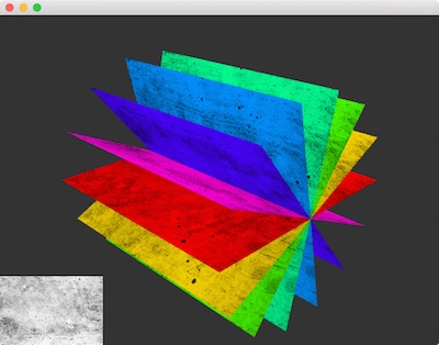
We've modified the previous example to multiply the solid color with a texture, using an image available here. Note that in the vertex shader, we're now using a variable ciTexCoord0, and outputting a matching TexCoord0. This vertex data is supplied by Cinder automatically, corresponding to geom::Attrib::TEX_COORD_0. This attribute is supplied by geom::Plane in our case. In the fragment shader, note the uTex0 uniform, which is of type sampler2D. This type corresponds to a texture sampler, which operates on a specific texture unit (not a Texture itself). Note that in setup() we call bind() on the texture, and pass it 0. This is the default value, but it's explicit here to highlight that there are multiple texture units. We specify this texture unit when we call mGlsl->uniform( "uTex0", 0 ) later.
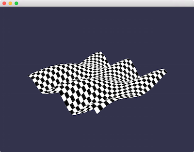
To sample from GLSL, we call the texture() function, passing it the sampler2D we'd like to sample from, and the texture coordinates to sample at. Again, we received the texture coordinates from geom::Plane automatically. However we could perform some sort of mathematical manipulation on them, or use these coordinates for other purposes. Let's try that now, in addition to looking at how to perform some more interesting manipulation in the vertex shader.
void BasicApp::setup()
{
	mCam.lookAt( vec3( 3, 2, 3 ), vec3( 0 ) );

	mGlsl = gl::GlslProg::create( gl::GlslProg::Format()
	.vertex(	CI_GLSL( 150,
		uniform mat4	ciModelViewProjection;
		in vec4			ciPosition;
		in vec2			ciTexCoord0;
		out vec2		TexCoord0;

		float offset( vec2 uv )
		{
			return ( sin( uv.x * 15.0 ) +
					cos( uv.y * 7.0f + uv.x * 13.0f ) ) * 0.1f;
		}

		void main( void ) {
			vec4 pos = ciPosition;
			pos.y = offset( ciTexCoord0 );
			gl_Position	= ciModelViewProjection * pos;
			TexCoord0 = ciTexCoord0;
		}
	 ) )
	.fragment(	CI_GLSL( 150,
		uniform float		uCheckSize;

		in vec2				TexCoord0;
		out vec4			oColor;

		vec4 checker( vec2 uv )
		{
			float v = floor( uCheckSize * uv.x ) +
							floor( uCheckSize * uv.y );
			if( mod( v, 2.0 ) < 1.0 )
				return vec4( 1, 1, 1, 1 );
			else
				return vec4( 0, 0, 0, 1 );
		}

		void main( void ) {
			oColor = checker( TexCoord0 );
		}
	) ) );

	auto plane = geom::Plane().subdivisions( ivec2( 30 ) );
	mRect = gl::Batch::create( plane, mGlsl );

	gl::enableDepthWrite();
	gl::enableDepthRead();
}

void BasicApp::draw()
{
	gl::clear( Color( 0.2f, 0.2f, 0.3f ) );
	gl::setMatrices( mCam );

	mGlsl->uniform( "uCheckSize", 30.0f );
	mRect->draw();
}