OpenGL in Cinder
Getting Started
Let's begin by looking at a minimal OpenGL application written with Cinder. This barebones app simply draws a blank, black window:
#include "cinder/app/App.h"
#include "cinder/app/RendererGl.h"
#include "cinder/gl/gl.h"

using namespace ci;
using namespace ci::app;

class BasicApp : public App {
  public:
	void draw() override;
};

void BasicApp::draw()
{
	gl::clear();
}

CINDER_APP( BasicApp, RendererGl )
In order to use OpenGL, a Cinder app instantiates app::RendererGl UNSTYLE using the CINDER_APP macro. The most straightforward way to start to use Cinder's OpenGL API is to #include "cinder/gl/gl.h". While this does not include all of Cinder's OpenGL headers, it does include some of the commonly used ones.
Convenience Functions
Often you're more interested in ease of implementation than performance. Cinder's ci::gl convenience functions are for this purpose. Let's look at how to use them to draw a filled circle. A modified version of the previous example's draw() method follows:
void BasicApp::draw()
{
	gl::clear();
	gl::drawSolidCircle( getWindowCenter(), 200 );
}
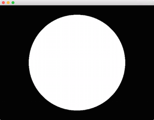
We're making use of the gl::drawSolidCircle() function, which takes a vec2 offset and a radius. This short example also highlights the fact that by default app::RendererGl sets up a coordinate system that matches the app::Window 1:1 in pixels. Later we'll look at how to manipulate the coordinate system.
Let's make another modification to the draw() method:
void BasicApp::draw()
{
	gl::clear();
	vec2 center = getWindowCenter();
	float r = 100;

	gl::color( Color( 1, 0, 0 ) ); // red
	gl::drawSolidCircle( center + vec2( -r, r ), r );
	gl::color( Color( 0, 1, 0 ) ); // green
	gl::drawSolidCircle( center + vec2( r, r ), r );
	gl::color( Color( 0, 0, 1 ) ); // blue
	gl::drawSolidCircle( center + vec2( 0, -0.73 * r ), r );
}
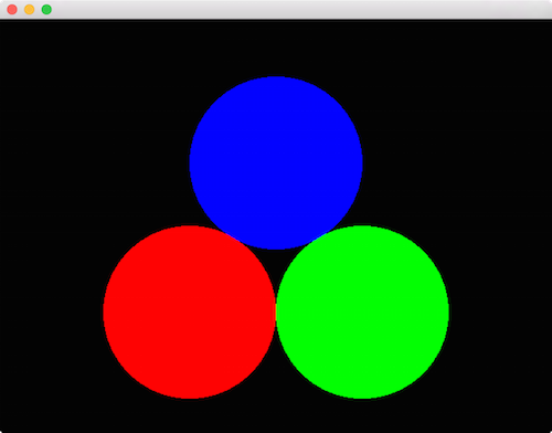
The snippet above highlights the gl::color() method. This sets a global current color, which the convenience methods make use of.
Transformations
Traditionally in computer graphics, transformations (operations like translation, scale and rotation) are implemented using 4x4 matrices. Cinder's Model matrix is a global transformation which is applied to any draw call. Routines like gl::translate(), gl::scale() and gl::rotate() manipulate the active Model matrix.
void BasicApp::draw()
{
	gl::clear();
	// reset the matrices
	gl::setMatricesWindow( getWindowSize() );

	// move to the horizontal window center, down 75
	gl::translate( getWindowCenter().x, 75 );
	gl::color( Color( 1, 0, 0 ) );
	gl::drawSolidCircle( vec2( 0 ), 70 );

	// move down 150 pixels
	gl::translate( 0, 150 );
	gl::color( Color( 1, 1, 0 ) );
	gl::drawSolidCircle( vec2( 0 ), 70 );

	// move down another 150 pixels
	gl::translate( 0, 150 );
	gl::color( Color( 0, 1, 0 ) );
	gl::drawSolidCircle( vec2( 0 ), 70 );
}
There's a couple of things to notice in this code, the first being the call to gl::setMatricesWindow(). This sets the Model matrix to Cinder's default, window-aligned configuration when passed the Window's current size (via getWindowSize()). If we did not call this, we would keep translating the Model matrix indefinitely, and our circles would quickly be too far down to see. This is because the effects of gl::translate() et al. are cumulative, meaning the operation is appended to the current Model matrix rather than replacing it. In the case above, a call to gl::translate( 0, 150 ) translates the current Model matrix 150 units vertically; note it does not set the translation to ( 0, 150 ).
Also key is to note that we draw the circles with an offset of (0,0) now, since we are relying on the Model matrix manipulated by gl::translate() to position them.
For many use cases, it can be convenient to preserve, manipulate and then restore the Model matrix. Cinder makes this simple by using a stack of matrices, coupled with the routines gl::pushModelMatrix() to push and preserve the Model matrix, and gl::popModelMatrix() to restore it. Let's take a look at an example of how this can be useful.
void BasicApp::draw()
{
	gl::clear();

	// preserve the default Model matrix
	gl::pushModelMatrix();
	// move to the window center
	gl::translate( getWindowCenter() );

	int numCircles = 16;
	float radius = getWindowHeight() / 2 - 30;

	for( int c = 0; c < numCircles; ++c ) {
		float rel = c / (float)numCircles;
		float angle = rel * M_PI * 2;
		vec2 offset( cos( angle ), sin( angle ) );

		// preserve the Model matrix
		gl::pushModelMatrix();
		// move to the correct position
		gl::translate( offset * radius );
		// set the color using HSV color
		gl::color( Color( CM_HSV, rel, 1, 1 ) );
		// draw a circle relative to Model matrix
		gl::drawStrokedCircle( vec2(), 30 );
		// restore the Model matrix
		gl::popModelMatrix();
	}

	// draw a white circle at window center
	gl::color( Color( 1, 1, 1 ) );
	gl::drawSolidCircle( vec2(), 15 );

	// restore the default Model matrix
	gl::popModelMatrix();
}
In this example, we preserve the default Model matrix by calling gl::pushModelMatrix() at the start of draw(), and calling gl::popModelMatrix() at the end. Note that we no longer need the call to gl::setMatricesWindow() as a result. Next, we translate to getWindowCenter(), so all subsequent draw calls are relative to the window's center. Then inside of a for-loop, we draw a series of circular outlines arranged in a circle whose radius is based on the height of the window. For each, we first do some basic trigonometry to determine the offset. Then we save a copy of the current Model matrix and translate by this offset. Recall that because these transformations are cumulative, this translation is relative to the window center, due to our earlier call to gl::translate(). Next we set the color using HSV color and draw a circle relative to the current Model matrix. We then restore the matrix (setting it to be the window center once again) using gl::popModelMatrix(). Finally, we draw a white circle at the window center and restore the matrix to its value when first entered draw().
If you're wondering if we could achieve the same thing simply by passing offset * radius as the first parameter to gl::drawStrokedCircle(), you're correct. Let's look at an example which could not be achieved without using transformations. Here we'll use the gl::scale() and gl::rotate() functions.
void BasicApp::draw()
{
	gl::clear();

	// preserve the default Model matrix
	gl::pushModelMatrix();
	// move to the window center
	gl::translate( getWindowCenter() );

	int numCircles = 32;
	float radius = getWindowHeight() / 2 - 30;

	for( int c = 0; c < numCircles; ++c ) {
		float rel = c / (float)numCircles;
		float angle = rel * M_PI * 2;
		vec2 offset( cos( angle ), sin( angle ) );

		// preserve the Model matrix
		gl::pushModelMatrix();
		// move to the correct position
		gl::translate( offset * radius );
		// rotate by current angle
		gl::rotate( angle );
		// non-uniform scale
		gl::scale( 8, 0.25f );
		// set the color using HSV color
		gl::color( Color( CM_HSV, rel, 1, 1 ) );
		// draw a circle based on the current Model matrix
		gl::drawSolidCircle( vec2(), 20 );
		// restore the Model matrix
		gl::popModelMatrix();
	}

	// restore the default Model matrix
	gl::popModelMatrix();
}
In this example, we demonstrate a couple of new things. For each circle, we start by scaling it non-uniformly, making it 8 times as wide and ¼ as tall, by passing ( 8, 0.25f ) to gl::scale(). We also gl::rotate() each circle (now oval) by an angle that matches its position in the circular arrangement. Last, we move each oval to its position in the circle using gl::translate(). Note however that we make these calls in the reverse order to how they occur conceptually. Specifically, we call gl::translate(), followed by gl::rotate(), followed by gl::scale(), but the effect we achieve is the reverse - scaling, then rotation, then translation. This reversed order of operations is typical for graphics APIs and will grow comfortable for you if it's not already. And of course all of this points to the fact that the order of operations does indeed matter:
void BasicApp::draw()
{
	…
	for( int c = 0; c < numCircles; ++c ) {
		…
		gl::translate( offset * radius );
		// reversed scale & rotate
		gl::scale( 8, 0.25f );
		gl::rotate( angle );
		gl::drawSolidCircle( vec2(), 20 );
		…
	}
	…
}
Here we've only swapped the order of the calls to gl::scale() and gl::rotate(), and it's obvious the order matters quite a bit. Consider what we're doing conceptually, keeping in mind that the operations are applied "in reverse" - they should be read from bottom-to-top relative to the draw call. First, we rotate by angle. However rotating a circle results in the same circle, so this achieves no effect. Next, we apply our non-uniform scale, creating an oval, and then finally we position the oval in the circular arrangement.
In the next section we'll look at how to take these concepts into 3D.